UMSATS TSAT-7 Payload Module
This project was an iteration of- and major improvement over- the TSAT-7 payload module.
Like TSAT-6, the purpose of the payload module is to house samples of Anaboena Cylindrica cyanobacteria. It includes 680nm LEDs to provide light energy, a resistive heater, and sensors to monitor both the temperature and the light level in the well.
The operating theory is that as the cyanobacteria multiplies, it increases the opacity of the medium that they are suspended in. Thus, less light is let through, which we can measure using the light level sensors.
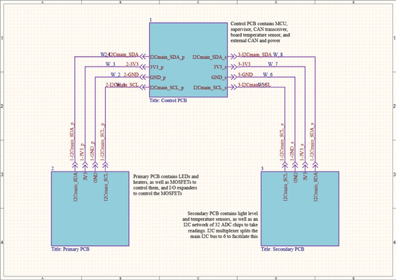
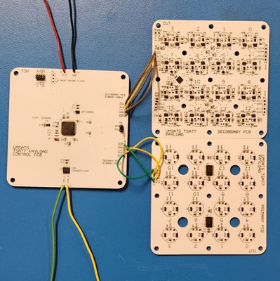
The system consists of 3 PCBs, all of which I designed and hand-assembled at the UMSATS lab at the University of Manitoba. PCBs were designed using Altium designer. The PCBs are as follows:
- Control PCB – contains the central processor (an ARM Cortex-M4 chip), some temperature sensing, differential CAN transceiver for communicating on the satellite bus, and connectors to the other 2 PCBs with power and I2C.
- Primary PCB – contains the LED emitters and the resistive heaters.
- Secondary PCB – contains the light sensing photoresistors and thermistors for temperature sensing.
Control PCB
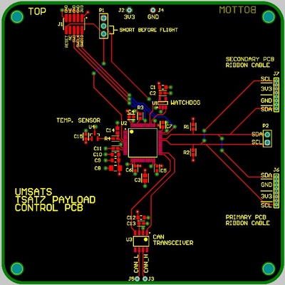
The control PCB is pretty barren. When assembled, this PCB sits on standoffs on top of the secondary PCB. There are two 8-pin ports for ribbon cable connections to the other two boards. A differential transceiver is used to connect to the satellite CAN (controller area network) bus. An external watchdog chip is used to supervise the microprocessor, and can be enabled by shorting two of the three pins located next to the programming header. The 10-pin programming header is used to flash firmware and for debugging.
Other than that, there’s a few passives, mostly extensive decoupling capacitors for every IC, and that’s it.
Since I knew it would be very helpful during debugging to be able to see what’s happening on the I2C line, I included a header to easily connect a logic analyzer to the I2C line.
Primary PCB
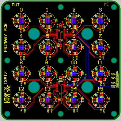
This PCB contains the LED emitters and the heater resistors. Since these are (relatively) high power devices, switching MOSFETs are used so that the microprocessor isn’t supplying power directly from it’s pins. There are 16 sample wells, each with one LED and one heater, so there are a total of 32 devices which need to be individually connected.
To avoid having to send 32 GPIO lines on a huge ribbon cable from the control PCB, two 16-pin I/O expanders are used. These control wells 0-7 and 8-15 respectively. The IO expanders are connected to the microprocessor via the “main” I2C bus (more about that later). This way, turning on or off a specific LED or heater is a simple I2C message.
Secondary PCB

This PCB is the most complex but also the one I’m the most proud of. This PCB required 32 sensors – a light level sensor and a temperature sensor for each of the 16 sample wells. I wanted to do this in an organized, elegant way. Preferably, I would like to be able to query sensor data from each well on some kind of shared connection – this made I2C the obvious choice.
The Sensors
Data collection at each sensor is done by a Microchip Technology MCP3221 single-ended single-input 12-bit ADC IC. I chose these since they have a small footprint, are I2C addressable, and have a sufficient resolution (12 bit) for this purpose. There was only one problem – these only come in 8 possible I2C address configurations, and I need 32 of them. To make matters worse, at the time of production, only 7 of those address configurations were available to purchase at any outlet. More on that later.
Temperature Sensors
Temperature sensing is done via a negative thermal coefficient (NTC) thermistor. This means that as temperature increases, resistance decreases.
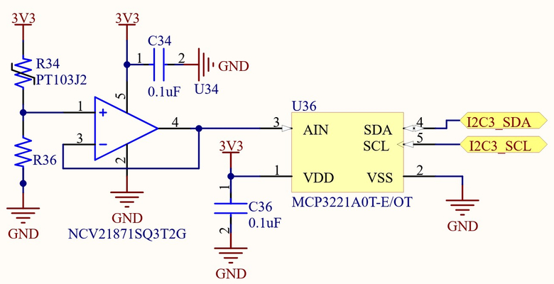
The thermistor in this circuit is R34. It is placed in series with R36 (a high accuracy 10k resistor) to produce a voltage divider. The voltage at this divider goes into a voltage follower buffer made from a low offset voltage op amp, which then goes into the input of the ADC. The voltage buffer is required because the input of the ADC is not high-impedance, so it needs to be driven with a small amount of current. Had I connected the ADC directly to the voltage buffer, there would be significant loading effect.
Light Level Sensors
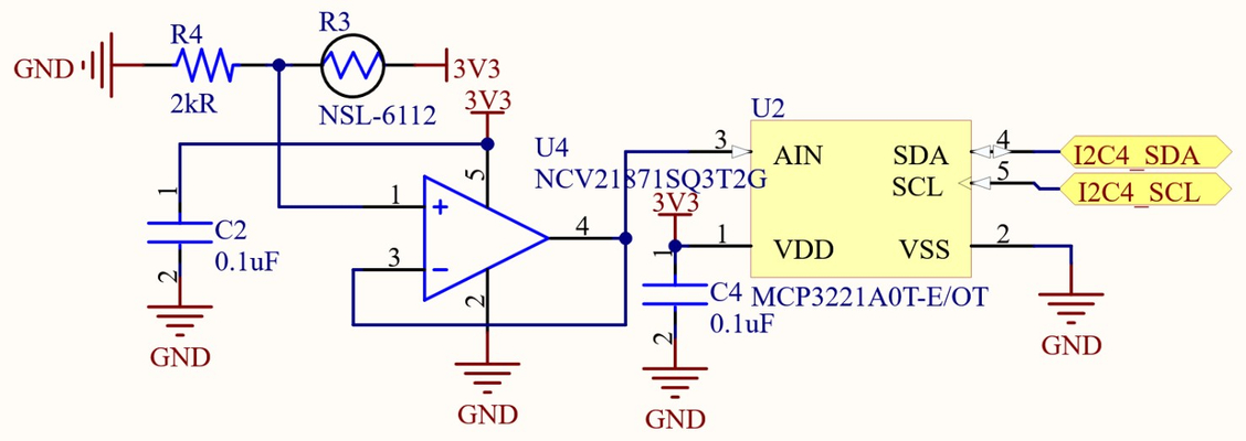
The light level sensors are similar to the temperature sensors. A light sensitive photoresistor is used instead of a thermistor, and the same voltage buffer is used.
The Multiplexer
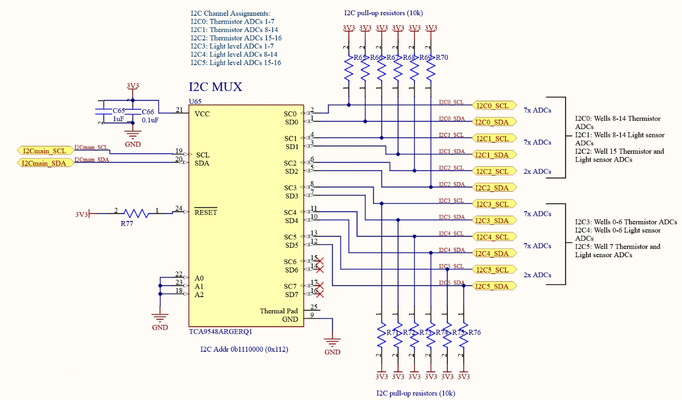
Like I mentioned before, I had 7 possible address configurations but needed 32 devices on one line. The solution was to split the I2C bus into multiple separate busses, and switch between them as needed, so that only one is active at a time.
The way to do this is using an I2C multiplexer. In this case, the Texas Instruments TCA9548. This is an I2C device which connects the main bus to any of the 8 I2C subchannels. To get a specific light level or temperature reading, the correct I2C channel and the correct address on that channel must be selected. I was initially worried about I2C bus capacitance, but given that there were maximum 7 devices on any physical circuit it was obvious that I wasn’t close to the recommended maximum capacitance on a single normal-speed line.
Manufacturing
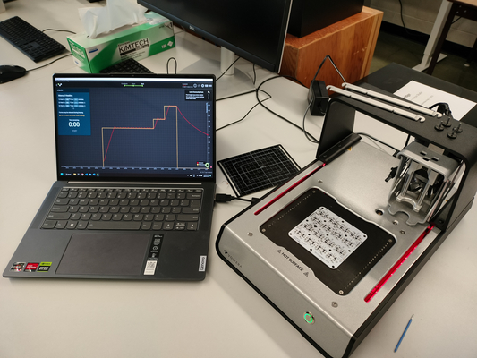
Solderpaste was applied with SMD stencils. I then hand placed each component with the help of a microscope to get a clearer picture. To solder, we used a programmable hot plate available in a different lab at the U of M to apply the recommended heating profile of the paste we were using.