Custom Wireless Voltage to MIDI Converter for Live Entertainment
This project is a custom design for a niche application and as such requires some explanation. It was a collaborative project. I designed the hardware and wrote the software, while a technician built the actual devices following my design and flashed the code I had written. I had a breadboard prototype which I used for testing.
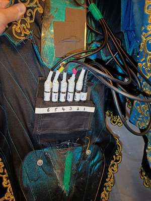
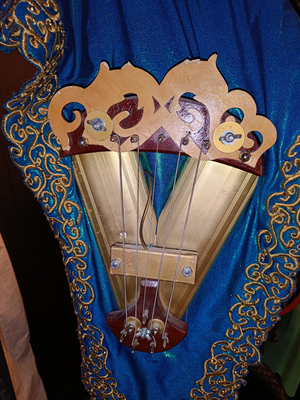
Modern theatrical productions are complicated, well-oiled machines. They feature all kinds of cool tech. In this production, certain members of the cast wore “wearable instruments” which they could play live on stage. One “instrument” was a dress which contained violin “strings” (actually bass guitar strings) which could be played with a Cello bow. The other was a jacket with pads on it which, when struck, would play a drum sound. The “drummer” could then pat the jacket like he was checking his pockets.
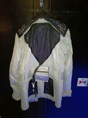
The problem is, those bass guitar strings don’t exactly make a nice, in tune sound when played with a bow and there’s no drums actually mounted in the jacket. Instead, these sounds come from a computer at the sound desk in the back of the theatre. I was tasked with designing a system that could send information about which “notes” are being played on the two wearable instruments to that computer, which would then play the appropriate sound. Since they would be played live in front of an audience, the requirements I identified were as follows:
- The connection must be low latency, such that the performer can play their “instrument” live. In this case, less than 15 milliseconds was considered acceptable.
- The connection must be reliable. One missed note is unacceptable.
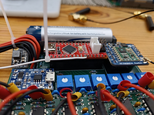
The Radios
I elected to use HopeRF RFM69HCW radio modules which are based on the Semtec SX1231 IC, and operate in the unlicensed 900MHz ISM band. I chose this band since I was concerned that something like 2.4GHz would be too congested in a large building like this, especially with hundreds of cell phones and other wifi connected devices in the building. These are nice little radios with lots of advanced features, and a maximum data transmission rate of 300kbit/second.
Communication with the RFM69 modules happens via SPI, so I wrote a custom driver that would configure the radios to the desired settings, and which would allow me to just pass a byte array into a helper function which would handle the SPI communication. I used a 16-byte preamble with a 2-byte payload to give the receiver lots of time to pick up an incoming message.
Using these radios, I achieved a point-to-point latency of 2 milliseconds. There would be more delay due to the sample buffer of the computer playing the sound than there would be because of this radio.
The Sensors
On the “violin dress” as it was called, the actual signals would be picked up by an electric guitar pickup. This meant that the incoming signal would be weak and needed to be conditioned and filtered. To do this, I designed a 3 stage circuit:
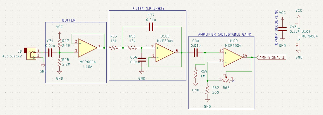
The first stage is a high impedance buffer – this is only there to present a high impedance input to the guitar pickup, since it can’t supply any signal power to a low impedance input. The second stage is a 2nd order Sallen-Key low-pass filter with a cutoff frequency of 1kHz. I chose this frequency to filter out all of the higher frequency noise coming from the many noise sources in a theatre. The third stage is an adjustable gain non-inverting amplifier. By adjusting a potentiometer, the sensitivity of this circuit can be set from A = 1 to A = 100,000.
An unintended byproduct of this process is that the output wave is half-wave rectified since there is no way to amplify the negative voltage as there is no negative supply in this circuit. That’s fine, since all I need to do is detect that the signal is there. I don’t care about the quality of any hypothetical audio. The filtered and amplified signal is then sent to an Analog-to-Digital converter pin of the Arduino which measures the incoming clean signal. I managed to fit the entire circuit on one DIP package IC with 4 op amps in it to save space, which was getting limited.
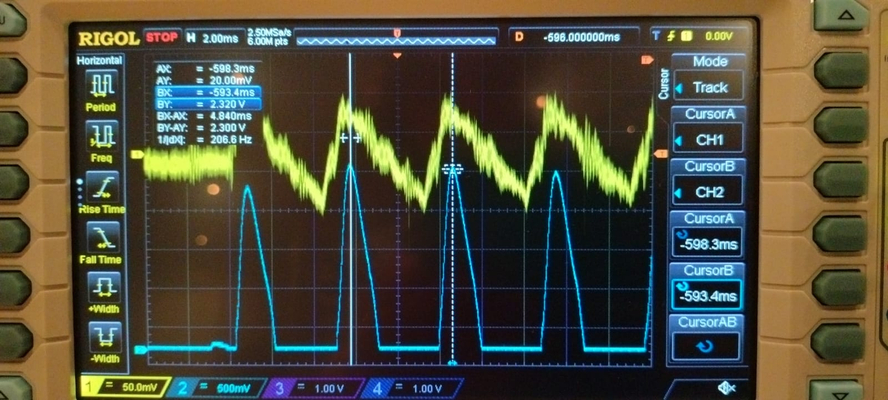
The difference between the input and output signals is night and day. It goes from noisy and weak, to strong and clear. (Note that the voltage scale of the two signals is very different – the output (blue) signal is MUCH stronger than the input).
The “drum jacket” used piezoelectric sensors which generated a sharp spike when struck, which was arguably easier to detect. The same signal conditioning circuit could be used without any modifications.
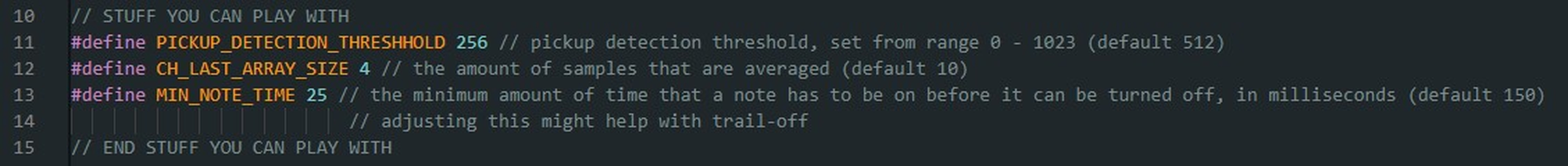
The Software
The nuance in the software comes from finding a balance between sensitivity and clarity. If I make the software too jumpy, it may detect multiple drum hits when only one occurred. In effect, I had to do some software debouncing, which in the case of the drum jacket I did by just having a timeout of a few milliseconds after a note was hit so that there were no inadvertent retriggers.
The bowed strings were more difficult. The signal is more dynamic, and a note could last for several seconds. I needed the software to be able to confidently determine when the player had started playing a note, and when they had stopped. I had no way of testing this. So I programmed in a number of variables that would influence how the Arduino would look for a note starting and stopping. The technician – who had no programming experience - could then experiment with these constants and fine tune the behaviour of the device to the performer’s liking, without having to sift through code.
Another nice addition that I could make because of the digital nature of the communication was what I called “check-ins” – an indicator LED on the receiver would light up if a signal was received from the transmitter. This could occur even if no notes are being played through a check-in byte, which would just let the receiver know that the transmitter was still active. If the receiver didn’t receive any note data or a check-in for a set time-out, the indicator LED would turn off. This way, the sound designer at the mixing desk can verify that there is a connection between the devices when they are turned on backstage before the actors actually perform.
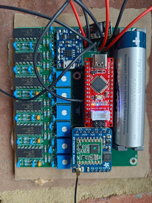
Battery System
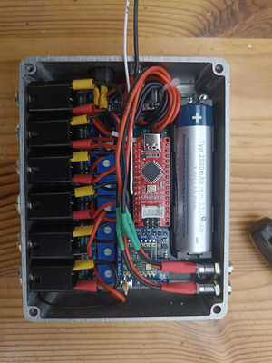
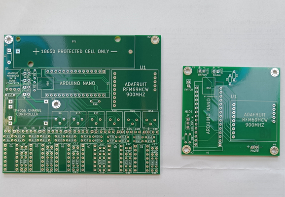
The Arduino has an ADC pin connected via a 10k resistor to the battery to monitor battery level. When the battery voltage drops below the 20% threshold of a standard lithium ion cell, the Arduino activates a red indicator LED to show that the battery is low and needs charging. Charging is done through a pre-made TP4056 battery management circuit – a tried and tested circuit. A 5V charge pump booster circuit is used to supply the 5V power needed for the Arduino. This was also pre-made.
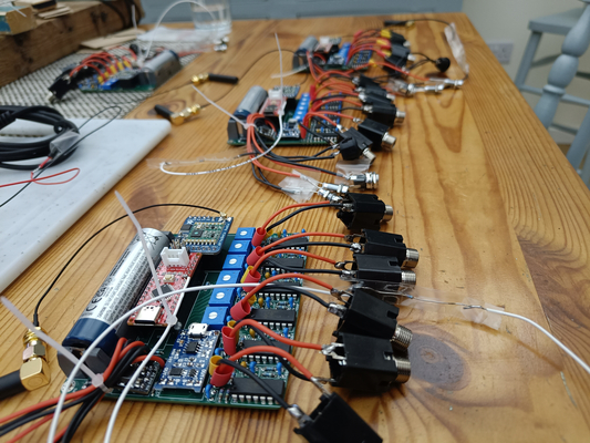
The Receivers
The receivers are not battery powered since they live at the mixing desk.
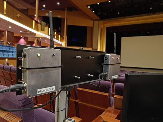
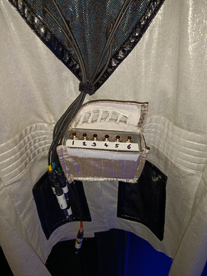
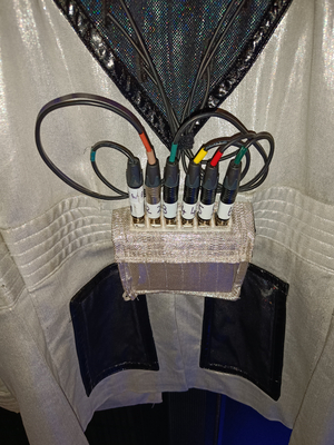
The receivers send note information to the computer playing the sounds via MIDI – a communication protocol designed for musical instruments. That’s the round connectors coming out of the bottom left side of the receiver. MIDI messages can be either note on or note off – the receiver sends these based on note on and note off data that it receives from the transmitter on stage.
The Final Product