The full PCB schematics for this project can be found on my Github page.
In observational astronomy, humidity is the enemy. At night, when temperatures dip below the dew point, moisture in the air begins to condensate on anything and everything. This includes the mirrors and lenses inside telescopes, which fogs up your view and brings your night to an early end. One way to combat this is to wrap the optics in a heated strap to warm it up and bring the surface of the optics above the dew point.
Commercially available options are quite expensive so I decided to have a crack at it myself. The main thing I want to focus on is the controller – this is a slow period variable duty cycle PWM generator that turns on and off a MOSFET, allowing current to flow through the resistive elements in the heater strap. By adjusting the duty cycle, the average power through the heater can be adjusted from 0W to ~12W.
I wanted to do this without the use of any microcontrollers. The PWM signal generators are 555 timer based, and the circuit looks like this:
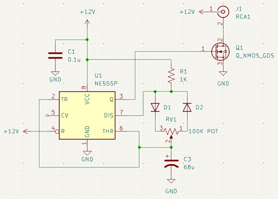
This operates by charging and discharging the capacitor C3. Initially, the capacitor is charging through the diode D1 and one part of the potentiometer. Once the capacitor reaches a specific threshold voltage (2/3 the supply voltage), the 555 timer starts discharging the capacitor through the other part of the potentiometer and the diode D2. This means that, depending on the position of the potentiometer, the capacitor will charge or discharge at different rates, and the charge and discharge rates will be inversely proportional to each other (if one increases, the other will decrease).
When the capacitor is charging, the output of the 555 timer is HIGH and the MOSFET Q1 is ON. When the capacitor is discharging, the 555 timer output is LOW, and the MOSFET Q1 is OFF. By controlling how long the capacitor spends charging and discharging, I can generate a PWM signal with varying duty cycle. The frequency of this cycle is approximately 0.1Hz, or a period of 10 seconds. In practice, this varies by a few seconds when the duty cycle is adjusted, but for this application that doesn’t matter.
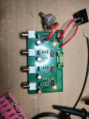
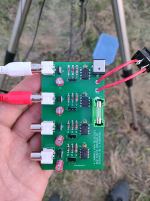
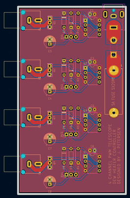
I took 4 of these circuits, put them on a PCB, added a fuse for good measure, and threw it all together. Not the use of RCA style audio connectors – these are friction fit, so if the telescope is accidentally slewed and the cable snapped taught, the connectors will simply slide out rather than risk snapping the cable or damaging something else. These connectors were a pain to create a custom PCB footprint for!
The heater elements are a large number of resistors soldered in parallel across two strips of copper tape, and then wrapped in duct tape to protect them. Cheap, but effective.
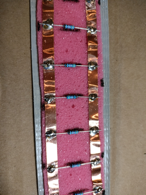
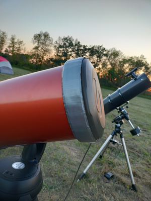
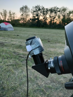
I made two heater strips – one for the main objective lens of my telescope and one smaller one for the telescope eyepiece.
Next up is to model and print a proper enclosure for this.